This website is actually a web interface for the RoCo python library. If you are
comfortable programming in python, you can also create your own designs for
different robots / objects.
Example
Here's an example, creating a six-sided die out of paper. How could you write a
program to describe a six-sided die?
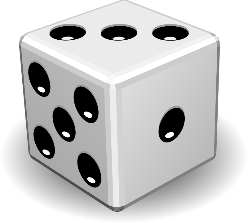
The first step is to draw out the flattened shape on paper. For a die we are
familiar with the shape (ignore numbers - they're for reference later).
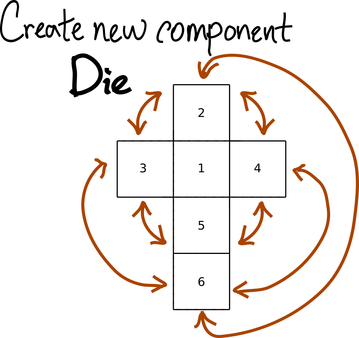
Now how do we tell a computer to do it? Here's one way of thinking about it:
- We have six squares
- We can write down which edges connect to which edges when folded
- We also write down the angle between edges when folded
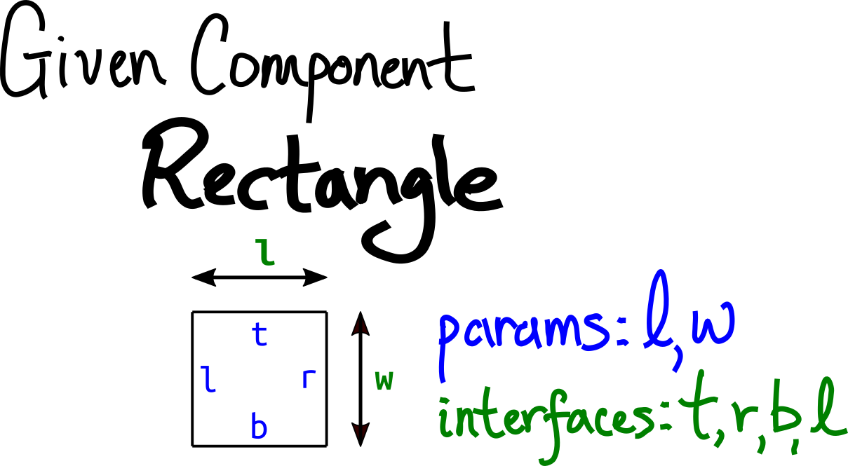
1. Create Squares
For creating the squares, it turns out there are pre-built components we can
use. We can use the Rectangle component, which is pre-specified to have parameters
length and width, as well interfaces on the
top/right/bottom/left sides.
We will create our component and start by adding six squares.
    from rocolib.api.component import Component
    c = Component()

    c.addSubcomponent("face1","Rectangle")
    ...  # same for faces 3, 4, 5
    c.addSubcomponent("face6","Rectangle")
To make a square, we'll set the width and length to be equal. We'll add a
custom parameter called length which we set to 50mm.
c.addParameter("length", 50)
And then use addConstraint to constrain l and w to both equal our custom
length parameter.
    c.addConstraint(("face1", "l"), "length")
    c.addConstraint(("face1", "w"), "length")

    c.addConstraint(("face2", "l"), "length")
    c.addConstraint(("face2", "w"), "length")
    ...  # same for faces 3, 4, 5
    c.addConstraint(("face6", "l"), "length")
    c.addConstraint(("face6", "w"), "length")
2A. Connect Edges (also specify angle when folded)
Next we will specify which edges connect to which edges, and the angle they
connect at when folded. For instance
the top of face1 should connect to the bottom of face2.
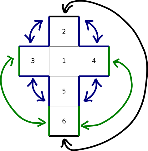
Just from the 2D picture we can start out with five such connections (highlighted
in orange below).
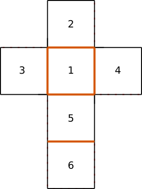
We can use the addConnection function to do so. We want the top edge of
face1 to connect to the bottom edge of face2. These are the t and b
interfaces respectively.
c.addConnection(("face1", "t"), ("face2", "b"), angle=-90)
We also specified an angle parameter - it's a 90 degree fold, and the negative
indicates a mountain fold (positive would be a valley fold).
So we have five total connections.
    c.addConnection(("face1", "t"), ("face2", "b"), angle=-90)
    c.addConnection(("face1", "l"), ("face3", "r"), angle=-90)
    c.addConnection(("face1", "r"), ("face4", "l"), angle=-90)
    c.addConnection(("face1", "b"), ("face5", "t"), angle=-90)
    c.addConnection(("face5", "b"), ("face6", "t"), angle=-90)
2B. Connect More Edges, now with Tabs
Now we can think about the edges which are not connected in our 2D picture but
are connected in 3D. If you count the green, blue, and black arrows below,
you'll see there are seven such connections.
When we're physically folding this together, we'll have to attach these edges
somehow, e.g. via glue or tape. The RoCo library can actually automatically
generate tabs for us! We just have to specify a tabWidth (note that tabs under
10mm hard to use).
We create the seven connections like so:
    c.addConnection(("face5", "l"), ("face3", "b"), angle=-90, tabWidth=10)
    c.addConnection(("face3", "t"), ("face2", "l"), angle=-90, tabWidth=10)
    c.addConnection(("face2", "r"), ("face4", "t"), angle=-90, tabWidth=10)
    c.addConnection(("face4", "b"), ("face5", "r"), angle=-90, tabWidth=10)

    c.addConnection(("face6", "l"), ("face3", "l"), angle=-90, tabWidth=10)
    c.addConnection(("face6", "b"), ("face2", "t"), angle=-90, tabWidth=10)
    c.addConnection(("face6", "r"), ("face4", "r"), angle=-90, tabWidth=10)
3. Presto!
Now we can use RoCo to generate our .stl 3d preview as well as our 2D
.svg and .dxf files for paper or lasercutter.
c.makeOutput("output/die50mm", tree=True, display=False)
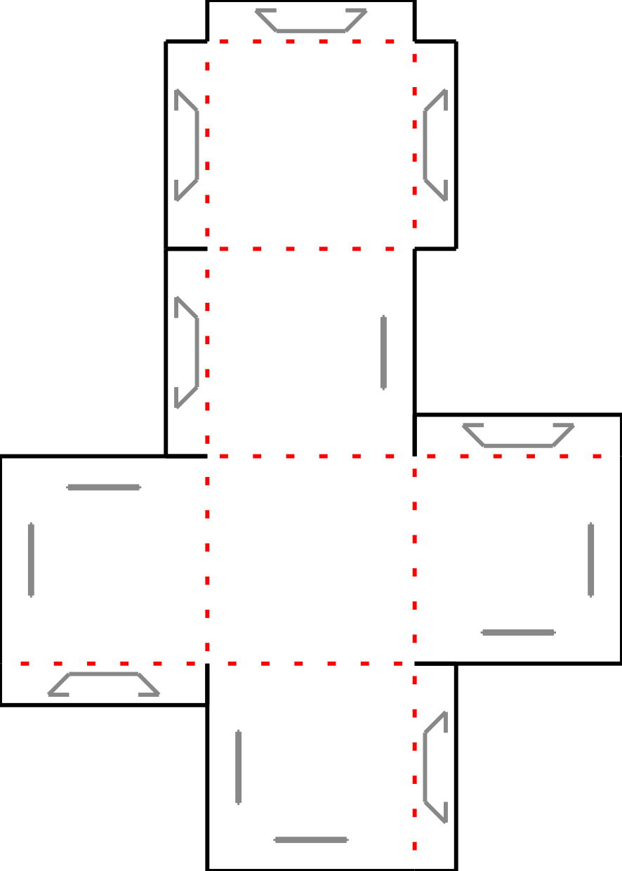
The tabs go into the slots (the gray lines) to hold the cube together.
The 3D file STL can be opened in applications such as MeshLab or Cura, here I
used OpenSCAD to open it and take a screenshot.
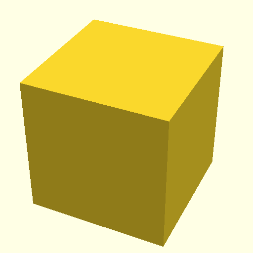
Pretty cool huh? :)
4. Extra Credit
We can also save our Die component for later use (e.g. as subcomponent for
something else) to the internal library which Roco automatically checks for.
c.toLibrary("Die")
After that, we can use our Die component anytime we want!
    from rocolib.library import getComponent
    d = getComponent("Die", length=65)
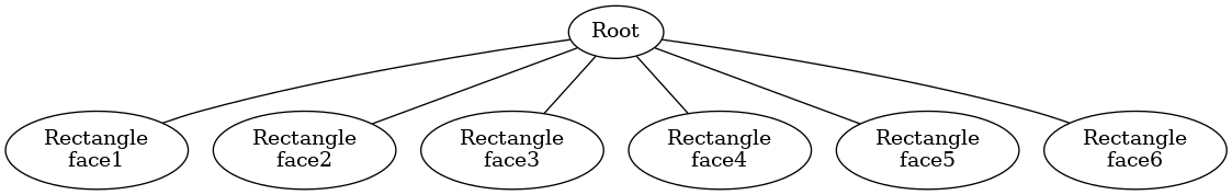
For fun, we can also see how the Rectangle subcomponents combined to make our
new Die component, in the tree.png file.
5. More Examples
For more examples, the source code for the components in this website can be found under the
"library" folder.
Some of the files in that folder are also generated using the scripts in the
"builders" folder.
You can run the file like so (after installing the library):
$ cat test_stool.py
from rocolib.library import getComponent
    f = getComponent('Stool')
    f.makeOutput('tests/pytest_output/Stool', display=False,
                 thickness=3) # 0.05mm for paper, 3mm for plywood

$ python test_stool.py
Appendix: Full Python file for creating die
The full file may be found at: die.py or copied in full below:
    from rocolib.api.component import Component
    # We're making a component
    c = Component()

    # ... 6 repeated squares
    c.addSubcomponent("face1","Rectangle")
    c.addSubcomponent("face2","Rectangle")
    c.addSubcomponent("face3","Rectangle")
    c.addSubcomponent("face4","Rectangle")
    c.addSubcomponent("face5","Rectangle")
    c.addSubcomponent("face6","Rectangle")

    # I pick one parameter, which is the lenght square side
    # let's say default = 50mm

    c.addParameter("length", 50)
    c.addParameter("tabWidth")

    # We need to constrain all parameters of all subcomponents to be functions of the parameter of our new component

    c.addConstraint(("face1", "l"), "length")
    c.addConstraint(("face1", "w"), "length")

    c.addConstraint(("face2", "l"), "length")
    c.addConstraint(("face2", "w"), "length")

    c.addConstraint(("face3", "l"), "length")
    c.addConstraint(("face3", "w"), "length")

    c.addConstraint(("face4", "l"), "length")
    c.addConstraint(("face4", "w"), "length")

    c.addConstraint(("face5", "l"), "length")
    c.addConstraint(("face5", "w"), "length")

    c.addConstraint(("face6", "l"), "length")
    c.addConstraint(("face6", "w"), "length")

    # pick out matching edges
    # (b2-c4) should fold at 90degrees (mountain fold, same for all folds)

    c.addConnection(("face1", "t"), ("face2", "b"), angle=-90)
    c.addConnection(("face1", "l"), ("face3", "r"), angle=-90)
    c.addConnection(("face1", "r"), ("face4", "l"), angle=-90)
    c.addConnection(("face1", "b"), ("face5", "t"), angle=-90)
    c.addConnection(("face5", "b"), ("face6", "t"), angle=-90)

    # in the folded state, (xx-yy) edges should be connected
    # We'll hold the edges together with tab/slot connections
    # The first argument will have a 10mm tab, the second will have the slot

    c.addConnection(("face5", "l"), ("face3", "b"), angle=-90, tabWidth=10)
    c.addConnection(("face3", "t"), ("face2", "l"), angle=-90, tabWidth=10)
    c.addConnection(("face2", "r"), ("face4", "t"), angle=-90, tabWidth=10)
    c.addConnection(("face4", "b"), ("face5", "r"), angle=-90, tabWidth=10)

    c.addConnection(("face6", "l"), ("face3", "l"), angle=-90, tabWidth=10)
    c.addConnection(("face6", "b"), ("face2", "t"), angle=-90, tabWidth=10)
    c.addConnection(("face6", "r"), ("face4", "r"), angle=-90, tabWidth=10)

    # And we're done!  We can make it right here right now, and the design files will end up in ./output/die/*

    c.makeOutput("output/die50mm", tree=True, display=False)

    # Or we can save it to our library to be used later
    c.toLibrary("Die")

    ### Now in another file we can make a larger die from our saved component

    from rocolib.library import getComponent
    d = getComponent("Die", length=65)
    d.makeOutput("output/die65mm", tree=True, display=False)